Replies: 18 comments 4 replies
-
|
I've used the Rockchip where it's appropriate - INAV is a real time system on metal, leveraging up to 1 MB of internal SRAM. As far as I can see, it's the opposite of what the Rockchip is appropriate for, the opposite of what it's designed for. To say a RK3506 is "superior" to an STM32F745 is a lot like saying a Sprinter delivery van Is far superior to a Corvette. The Sprinter is better fit for delivering wedding cakes; the Corvette is far superior for racing. The Rockchip and the STM are completely different categories of chips, designed for very different types of tasks. If you have an application where you need to connect INAV via wired Ethernet and have an operating system running other applications simultaneously on the same chip, and have the room for a larger board carrying an external DRAM module, the RK3506 may be a reasonable choice. Though there are other choices I would look at too for such as application. You'd absolutely need to make sure one core is 100% devoted to INAV and no interrupts will get in the way, causing the motor output or other things to glitch out for a fraction of a second. The ESCs MUST be updated several thousand times per second - a few milliseconds lost to multitasking is not okay. From experience with similar chips, if you have such a project plan on rather than a 20x20 FC you'll need around 30mm x 80mm. Remember the Rockchip CPU needs several additional external chips to be able to function - external RAM, external flash, etc. These are built-in to MCU chips like the STM32 series; CPUs like the Rockchip need a motherboard with all that stuff. The Rockchip used to be a good fit for OpenHD, because that job is reading the camera (via the Rockchip camera interface), processing the video through several external Linux programs (loading them to external RAM and processing them using the multiple Rockchip cores), then sending the video feed out via the Wi-Fi. So it was a good chip for OpenHD (for a while). |
Beta Was this translation helpful? Give feedback.
-
|
There is some misunderstanding |
Beta Was this translation helpful? Give feedback.
-
|
Offtopic |


Beta Was this translation helpful? Give feedback.
-
|
Ah that's true - there is an internal DRAM option with the Rockchip. Here's the introductory statement of what the Rockchip chip is, from it's datasheet:
Okay, so that chip is for multimedia processing - audio, images, and video, including displaying on a monitor. OpenHD is a media application, so the Rockchip fit that use case. Talking about MIPS capacity is like talking about pounds of cargo capacity a vehicle can carry. An F-250 has a capacity of 4000 pounds; the Corvette 425 pounds. Therefore the F-250 is better and everyone should drive an F-250 dually? No, not at all. The F-250 is better ONLY if you have a need to carry heavy cargo. If carrying heavy cargo is not your goal, the 4,000 pound cargo capacity is wasted and pointless. INAV uses about 200 DMIPS. Any additional is wasted and pointless. Meaning 98% of the DMIPS of the Rockchip would be running no-op, doing nothing at a high rate of speed. Wasting a lot more cycles doing nothing is not a benefit. It would be the same as buying an F-250 to run slalom. Choosing the F-250 over the 'vette for slalom, because the F-250 has a larger cargo capacity. The Rockchip is a good chip. Good at what it is designed for. As the manufacturer clearly states, it is designed for:
That's what it's good at.
It is. And it's silly to compare a pizza to a torque wrench. |
Beta Was this translation helpful? Give feedback.
-
|
That's cool you got MC running. I hope you find a cool use for your Rockchip multimedia processor. It has hardware accelerators for video encoding and decoding, which was important for OpenHD. You could use it as a flight computer, analyzing the video feed and issuing commands to INAV over MSP. That application requires processing throughput (DMIPS) and can tolerate many milliseconds of latency from the multitasking OS. Vs a flight controller, which needs 98% less throughput (DMIPS), and cannot tolerate several milliseconds of latency. Or maybe as an intelligent doorbell camera setup kinda like Ring cameras, but without the monthly fee. Or run OpenHD on it. Ps - you probably CAN run the INAV SITL on it. But don't expect to fly with it! The computer might decide to go do something else for eight or ten loops and the aircraft may crash. |
Beta Was this translation helpful? Give feedback.
-
|
This is very strange. I can set up a timer and execute the task on interrupts. A fast processor will eliminate task overlap. This is significantly more accurate than inav, which can't start the next task until the previous one has completed. And tasks can be long, you can check this with the tasks command. |
Beta Was this translation helpful? Give feedback.
-
|
Look at the latency to run the task from that timer interrupt. The last time I looked at doing that, just maximum latency of the hardware portion alone was about 20X too high for my application. I think you'll find that if you're running on bare metal (no OS), the interrupt latency can be hundreds of µs at least. If you're using the Rockchip as intended, with Linux, there is no upper bound - it could take many seconds. You first have the hardware latency of maybe 250 µs or whatever it is, then it checks the masks, then you wait for any kernel tasks, then any higher priority or earlier interrupts. Then all state has to be preserved. God help you if that means flushing pages.
INAV running on an MCU will take EXACTLY the same number of cycles every time. It's as accurate as your clock crystal. You can look at the hex and count the number of clock cycles for any function. It will always take exactly that long, down to the hundredth of a microsecond.
Kinda the opposite. When you look at MIPs, that's throughput, how many operations it can perform in an hour. A delivery truck can carry 3,000 pounds across the city in one afternoon - that's also throughput. Your ESC will be delivered sometime between noon and 9:00 PM, depending on the other stops the truck makes, traffic, and routing. That's a high throughput (DMIPS) mechanism. If I cross the street to hand you an envelope, that's low throughput - just one little envelope, carried a very short distance. It will always take me 8-9 seconds to cross the street, every time. Again, I totally understand wanting to do a cool project with a new piece of hardware. This particular hardware is a multimedia chainsaw, not a scalpel. OpenHD or a video-based flight computer would be good projects for that hardware, they would fit what that device does well. If you would like to try implementing this, you are of course welcome to try. I'll even point out some things you'll need to watch for, based on having been involved in a somewhat similar project. I will not be trying to slice cheese with a chainsaw. Not without a darn good reason. |
Beta Was this translation helpful? Give feedback.
-
|
Understand, Thank you. |
Beta Was this translation helpful? Give feedback.
-
Yes, if you get rid of the operating system and run it on a single core that gets you a lot closer to what you need. Direct control of the registers and scheduling / timing, so you know exactly how many cycles it will take to do X. |
Beta Was this translation helpful? Give feedback.
-
|
Well. Real tests
// gpio_timer.c
#include <linux/module.h>
#include <linux/init.h>
#include <linux/gpio.h>
#include <linux/hrtimer.h>
#include <linux/ktime.h>
#include <linux/math64.h>

// GPIO Configuration
#define MY_GPIO_PIN 2  // ???? GPIO0_A2_D = 26 (проверьте документацию!)
#define DESIRED_FREQ 12800
#define SAFETY_MARGIN_NS 5000  // 5 мкс запас

static struct hrtimer gpio_timer;
static ktime_t base_time;
static ktime_t timer_interval;
//static int gpio_state = 0;
static u64 period_count = 0;

// High-Resolution Timer Callback with ABS mode and safety checks
static enum hrtimer_restart timer_callback(struct hrtimer *timer)
{
    ktime_t now, safe_now, next_time;
    u64 interval_ns = ktime_to_ns(timer_interval);
    u64 ns_since_base;

    // Быстрое переключение GPIO
    //gpio_state = !gpio_state;

    gpio_set_value(MY_GPIO_PIN, 1);


    // Расчет следующего абсолютного времени
    period_count++;
    next_time = ktime_add_ns(base_time, period_count * interval_ns);

    // Проверяем, не находится ли next_time в прошлом
    now = ktime_get();
    safe_now = ktime_add_ns(now, SAFETY_MARGIN_NS);  // Добавляем запас 5 мкс
    ns_since_base =0;

    if (ktime_compare(next_time, safe_now) <= 0) {
        // Время в прошлом, вычисляем следующее доступное время в будущем
 /*       ns_since_base = ktime_to_ns(ktime_sub(safe_now, base_time));

        // Вычисляем следующий период, который будет в будущем
        period_count = div64_u64(ns_since_base + interval_ns - 1, interval_ns);
        next_time = ktime_add_ns(base_time, period_count * interval_ns);

        printk(KERN_WARNING "GPIO Timer: Time correction applied. New period_count: %llu\n",
               period_count);
 */
    }	else
    {
    gpio_set_value(MY_GPIO_PIN, 0);
    }

    // Устанавливаем следующее срабатывание
    hrtimer_set_expires(timer, next_time);


    return HRTIMER_RESTART;
}

// Module Initialization
static int __init gpio_timer_init(void)
{
    int ret;
    ktime_t first_expire;

    printk(KERN_INFO "GPIO Timer Module: Initializing with ABS+HARD mode and safety margin\n");

	struct task_struct *task = current;
	task->prio = 1;  // Высокий приоритет (меньшие числа = выше приоритет)


    // Расчет интервала для 12.8 kHz
    // Период = 1/12800 = 78.125 мкс, полупериод для toggle = 39.0625 мкс
    timer_interval = ktime_set(0, 156250);

    // Проверка и настройка GPIO
    if (!gpio_is_valid(MY_GPIO_PIN)) {
        printk(KERN_ERR "GPIO Timer Module: Invalid GPIO pin %d\n", MY_GPIO_PIN);
        return -ENODEV;
    }

    ret = gpio_request(MY_GPIO_PIN, "gpio_timer");
    if (ret) {
        printk(KERN_ERR "GPIO Timer Module: Failed to request GPIO %d, error %d\n", MY_GPIO_PIN, ret);
        return ret;
    }

    ret = gpio_direction_output(MY_GPIO_PIN, 0);
    if (ret) {
        printk(KERN_ERR "GPIO Timer Module: Failed to set GPIO %d as output, error %d\n", MY_GPIO_PIN, ret);
        gpio_free(MY_GPIO_PIN);
        return ret;
    }

    // Инициализация базового времени и первого срабатывания
    base_time = ktime_get();
    first_expire = ktime_add_ns(base_time, ktime_to_ns(timer_interval));

    // Инициализация и запуск высокоточного таймера в ABS+HARD режиме
    hrtimer_init(&gpio_timer, CLOCK_MONOTONIC, HRTIMER_MODE_ABS_HARD); 	//
    gpio_timer.function = &timer_callback;
    hrtimer_start(&gpio_timer, first_expire, HRTIMER_MODE_ABS_HARD);		//

    printk(KERN_INFO "GPIO Timer Module: Started at 12.8 kHz on GPIO %d\n", MY_GPIO_PIN);
    printk(KERN_INFO "Base time: %lld ns, Interval: %lld ns, Safety margin: %d ns\n",
           ktime_to_ns(base_time), ktime_to_ns(timer_interval), SAFETY_MARGIN_NS);

    return 0;
}

// Module Cleanup
static void __exit gpio_timer_exit(void)
{
    int ret = hrtimer_cancel(&gpio_timer);
    if (ret)
        printk(KERN_INFO "GPIO Timer Module: Active timer was cancelled\n");

    gpio_set_value(MY_GPIO_PIN, 0);
    gpio_free(MY_GPIO_PIN);

    printk(KERN_INFO "GPIO Timer Module: Exited after %llu periods\n", period_count);
}

module_init(gpio_timer_init);
module_exit(gpio_timer_exit);

MODULE_LICENSE("GPL");
MODULE_AUTHOR("My Name");
MODULE_DESCRIPTION("12.8 kHz GPIO Toggler for Luckfox Lyra (ABS+HARD mode with safety)");
MODULE_VERSION("0.3"); |

Beta Was this translation helpful? Give feedback.
-
|
Ok Now INAV void FAST_CODE NOINLINE scheduler(void)
{
// gyro task
GyroDiv = (uint32_t) micros();
GyroMod = GyroDiv % 159;
GyroDiv = GyroDiv / 159; // 1/6400
if((PrevGyroDiv != GyroDiv) || (GyroMod <10))
{
IMUUpdate();
PrevGyroDiv=GyroDiv;
}
// Cache currentTime
const timeUs_t currentTimeUs = micros();
// The task to be invoked
cfTask_t *selectedTask = NULL;
uint16_t selectedTaskDynamicPriority = 0;
bool forcedRealTimeTask = false;
// Update task dynamic priorities
.......... So st32f722 doesn't really look like a good choice for real-time tasks. |


Beta Was this translation helpful? Give feedback.
-
|
I appreciate your attempt to measure something. The issue isn't that it can't do something fast for a few milliseconds. The issue that it's multitasking, it does your thing fast for a few milliseconds, then goes off to do something else for few milliseconds. Kinda like a dump truck can deliver 5,000 pounds of gravel in only a few minutes. And it will arrive sometime between noon and 6 PM. And that's controlled by the company dispatcher, not by you the customer. The Linux task scheduler chooses when to run each task, completely outside of your control. And the maximum allowed latency under the kernel scheduler is -- infinite. Linux is 100% allowed to run your code tomorrow. Vs with an MCU, we're running our own scheduler. We decide how much latency is okay for each task. And we have control of that down to the clock frequency.
To output DSHOT, you need to toggle the pin at 0.625 µS. So your test shows that your Linux implementation is at least 640 times too slow. Really, 2,560 times too slow, if we figure you need your output to be within 25% of correct to the spec. INAV of course does DSHOT all day long on STM. Just curious - is there any particular reason you're trying to force a multimedia media CPU to emulate an MCU? Any reason to use your chainsaw for slicing cheese? |
Beta Was this translation helpful? Give feedback.
-
|
I always thought Dshot worked on PWM, but it's hardware-based and doesn't depend on CPU performance at all. You just need a free timer. Reverse Dshot is more complicated, but it can also be solved with timers. Although it's not in INAV. I would have long ago migrated ESC to something hardware-based like UART, I2S, SPI. I think that's a solution for the near future. All those -shots are just relics of PWM. And this trouble will fade into oblivion. |
Beta Was this translation helpful? Give feedback.
-
|
Yes, DSHOT is greatly assisted by the hardware capabilities of MCUs like the STM series. I have done DSHOT reception. It's doable on most MCUs once you figure out how. Very easy on a Pi Pico. Every week I use an ESP32 implementation I wrote. I wouldn't dare try it on the Raspberry Pi that is attached to the ESP32, or on my laptop. My FC tester is an MCU board attached to a Raspberry Pi with a touchscreen. The MCU is for microsecond timing. The CPU is for the graphical interface.
The issue is you probably have a total of no more than six UARTs. One for GPS, one for receiver, one for VTX, and then you have three left to run three motors? You could use SPI - with four data wires per ESC, as opposed to one. |
Beta Was this translation helpful? Give feedback.
-
|
This is not a problem. There is rs485. It based on uart technology (Although I don’t understand who is whose follower.) It has great noise immunity, but need separate drivers. These drivers cost nothing to mass produce. Serious drones use can. |
Beta Was this translation helpful? Give feedback.
-
RS-485 is an electrical specification. Voltage levels. |
Beta Was this translation helpful? Give feedback.
-
|
https://knowledge.ni.com/KnowledgeArticleDetails?id=kA0VU0000008zG10AI&l=en-US |
Beta Was this translation helpful? Give feedback.
-
|
Most devices nowadays are 1/4 UL, so you can do 128. Less than about 10 meters, we use RS-232 (depending on the speed you need). Less than about 10 centimeters, just connect the logic level directly - no need for a driver. RS-485 is most used in factories and such, where you have hundreds of meters of wiring. Where you will have seen it in person is stage and nightclub lighting systems. Those cables have to run from the control booth, up to the high ceiling, down the house, and to each light. The two XLR plugs you see sticking out of the back of each light are running DMX over RS-235 at 250 kbit/s. |
Beta Was this translation helpful? Give feedback.
-
|
I must confess to a degree of scepticism. The utilisation of a non-differential, unprotected CMOS interface with a 3.3V signal level in systems carrying currents up to 300A strikes one as thoroughly questionable practice. This invariably leads to failure modes such as data corruption or, indeed, the outright combustion of the input stage. These arrangements are vestiges of the amateurish constructions from which this field emerged a decade ago. In commercial-grade electronics, which drones have now become, this is quite inadmissible. In such instances, I invariably advocate for the implementation of galvanic isolation. The latter is now both cost-effective and readily procurable. |
Beta Was this translation helpful? Give feedback.
-
|
If you're running 300 amps, you need at least 00 AWG "wire" (copper rods) 3/4" thick, are well beyond the intended use of INAV - and should probably be running higher voltage. :) Anyway, you have 3.3V logic regardless. Sticking a pair of 48V drivers in between your two 3.3V logic pads does nothing but waste board space. I have noticed you have a habit of seeing a random part of some kind, then trying to shoehorn that random item as a solution to some imagined fantastical problem, as opposed to looking for the best solution to an actual problem. That's not my cup of tea, so I will bow out. I like to spend my time solving actual problems. You may enjoy spending your time starting with the thought "drones should use shampoo", then try to figure out a theory of why shampoo would be good for drones. |
Beta Was this translation helpful? Give feedback.
-
|
Well, one is simply curious about iNav and wishes to improve it. What I could manage on my own, I have already done. So, what is it you expect from iNav? I took my PhD in Semiconductor Physics in 2004 and have been working in the field ever since. My first assignment was to develop a DSP-based synchronous demodulator on an ADSP, which I later ported to the Shark processor. Consequently, the algorithms employed in iNav are, on the whole, quite familiar to me, as are the various data interfaces. In my professional capacity, I am primarily engaged in low-level signal measurements using both DC and AC currents. I therefore have a sound understanding of the genesis of electrical interference and its potential consequences. From the data I have presented, it is quite evident that the ST32F722 has been wanting in performance for some time. For any meaningful further development, a change of platform is rather imperative. Since the F722's introduction around 2017, and the F745 around 2015, a respectable number of alternatives have emerged which offer a marked superiority over the ST32, both in available memory and computational power. I merely cited the Rockchip as an illustration, as it happened to be at hand. And what, if I may ask, can you furnish beyond mere words? With wiring, the cross-section is not the only consideration. One must account for length, permissible temperature rating, the cooling regime, and the duty cycle. The allowable voltage sag is also of interest. If the battery itself sags by 2V under maximum load, then half a volt lost in the wiring is rather neither here nor there. After such optimisation, one finds that a 14-16 AWG wire is generally quite adequate. Well, my own engineering education is evidently not comprehensive enough, for such a novel application of shampoo had quite escaped me. |
Beta Was this translation helpful? Give feedback.
-
|
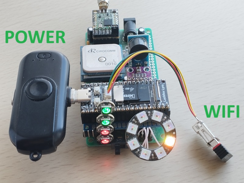
Luckfox Lyra (RK3506) upgrade for SoftRF Standalone Edition
|
Beta Was this translation helpful? Give feedback.
Uh oh!
There was an error while loading. Please reload this page.
-
I've been developing a small device and discovered that processors have long been available that are many times superior to the ST32 series, with similar dimensions and power consumption.
https://wiki.luckfox.com/Luckfox-Lyra/Introduction
Rockchip-RK3506G2.pdf
Beta Was this translation helpful? Give feedback.
All reactions